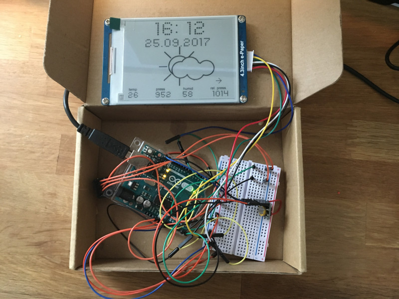
If you are Using the LCD shield it will look like the image below after mounting. Note that the RW pin is connected to GND because we will be writing only to the LCD and not to read from it, for this to be possible the RW pin has to be pulled LOW. Wire up your component as shown in the image below. This shield makes connecting the 16×2 LCD module to any system quite easy, as it simply just plugs on the Arduino mega which is being used for this project.

Yes, we will also be using the 16×2 LCD keypad shield as used in the previous tutorial. This sensor has three pins, the first which is the power pin VCC, next pin which is the middle one, which is the signal out or DATA pin and lastly the ground pin labelled GND.

The readings from this sensor are fairly accurate, so we will be using this sensor to only measure humidity since the BMP180 gives more accurate temperature readings.

It costs about $2 and you can get it here. The DHT11 is something we are familiar with, it has been used in couple of our tutorials here as a low cost temperature and humidity sensor that operates using the 1-wire protocol. This sensor is a four pin device, the first pin is labelled VCC, second pin GND and the last two are the clock (SCL) and data (SDA) pins.


 0 kommentar(er)
